

Networkable Analogue Addressable Fire Alarm Panel XFP
NETWORKABLE ANALOGUE ADDRESSABLE FIRE ALARM PANEL XFP
Context Plus’s XFP range of networkable analogue addressable fire panels offer high performance at a competitive price.
Certified to the latest versions of EN54 parts 2 & 4 by the Loss Prevention Certification Board, two versions are available – a cost-effective single loop 16 zone panel in a plastic enclosure and a robust 1 or 2 loop 32 zone metal panel.
Ideal for use in office blocks, shopping complexes and big industrial sites as well as smaller stand-alone applications, both versions offer an array of user and installer-friendly features, including:-
- Full compatibility with Apollo’s XP95/Discovery and Hochiki’s ESP protocols
- The ability to interconnect up to eight XFP main panels (any variant) onto a two wire RS485 network. Alternatively, up to eight XFP repeaters can be connected to a non-networked XFP main panel
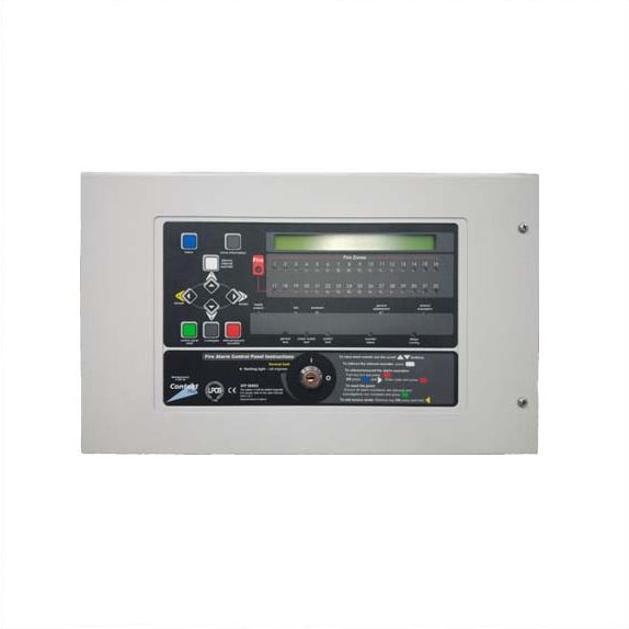
- Combined keypad / keyswitch entry to Access Levels 2 & 3
- Two independently programmable conventional sounder circuits
- Two programmable inputs
- A fault output relay and three programmable relay outputs with voltage free changeover contacts
- Three zone dependency functions (A, B & C to EN54-2 Clause 7.12) A day/night (building occupied/unoccupied) function
- An investigation delay period function
- Individual sensitivity settings for each device
- A phased evacuation and delays to outputs facility (to EN54-2 Clause 7.11)
- An alarm counter that records the number of times the panel has been in an alarm state (to EN54-2 Clause 7.13)
- Powerful short circuit protected loop drivers, capable of supporting up to 40 loop
- powered 10mA sounders per loop
- An integral EN54-4/A2 switch mode PSU rated @ 185-260V a.c. 50/60Hz (1.4A on a 16 zone panel, 3A on a 32 zone panel)
- Earth fault monitoring
- An easy to read, 80 character back-lit display
- 40 characters of custom text per device
- 999 event monitoring
- Comprehensive test facilities (to EN54-2 Clause 10) and a wide range of maintenance & commissioning functions including auto-learn loops, monitor a point, test outputs, one man walk test and loop continuity test
- An intuitive Windows based upload-download PC program that allows the system to be programmed quickly and easily
- Full compatibility with Context Plus’ Hush Button fire alarm solution for houses of multiple occupation
- Optional flush-mounting stainless steel enclosures available (for 32 zone XFP panels only)
| Power Supply Specification | SINGLE LOOP 16 ZONE XFP PANELS XFP501E/X; XFP501E/H |
ONE OR TWO LOOP 32 ZONE
XFP PANELS
XFP501/X; XFP501/H; XFP502/X; XFP502/H
|
| Mains supply | 230V a.c. ± 10% 50/60Hz. Max current 350mA |
230V a.± 10% 50/60Hz. Max current 680mA
|
| Internal power supply | 27V d.c Nominal | 27V d.c Nominal |
| Total output current limited to | 1.4A @ 230V a.c. | 3A @ 230 V a.c. |
| Power rating | Imax. a = 210mA; Imin. = 40mA |
Imax. a = 250mA (1 loop) 270mA (2 loop); Imin. = 70mA
|
| Maximum internal resistance | Ri max. - 1.1Ω | Ri max. - 1.1Ω |
| Supply and battery charger monitored for failure arge | Yes | Yes |
| Batteries monitored for disconnection and failure | Yes | Yes |
| Batteries protected against deep disch | Yes | Yes |
| Max. battery size and type | 3.2 Ahr VRLA | 7.0 Ahr VRLA |
| Specified batteries for LPCB approved systems | 2 x Yuasa NP3.2-12 | 2 x Yuasa NP7-12 |
| Quiescent current drain | < 50mA (1 loop unloaded) |
< 80mA (1 loop unloaded); <100mA (2 loops unloaded)
|
| Earth fault monitoring | Yes (any conductor) |
Yes (any conductor)
|
| Temperature compensated charging | Yes | Yes |
| Loop Driver Specification | ||
| Number of loop drivers | 1 |
1 (XFP501/X ; XFP501/H); 2 (XFP502/X, XFP502/H)
|
| Line monitored for open and short circuit faults | Yes | Yes |
| Onboard loop isolators with LED indication when active | Yes | Yes |
| Auto-polling from each loop end | Yes | Yes |
| Max. loop output current | 500mA (Voltage: 25V min, 34V max) |
500mA (Voltage: 25V min, 34V max)
|
| Max. number of addressable devices per loop | 126 | 126 |
| Max. number of loop powered sounders per loop @ 10mA | 40 | 40 |
| Number of programmable sounder groups | 16 | 16 |
| Number of programmable output sets | 16 | 16 |
| Conventional Sounder Circuit Specification | ||
| Number of programmable circuits | 2 | 2 |
| End of line resistor value | 6800 Ω 5% Tol. 0.25 W | 6800 Ω 5% Tol. 0.25 W |
| Line monitored for open and short circuit faults | Yes | Yes |
| Outputs fused at | 400mA. Protected by resettable overload circuit |
400mA. Protected by resettable overload circuit
|
| Output voltage | 19.5V minimum; 28V maximum |
19.5V minimum; 28V maximum
|
| Max. number of sounders @ 20mA | 40 | 80 |
| Auxiliary Outputs | |
| Type |
Relay voltage free single pole changeover
|
| Max switching current | 1A |
| Max switching voltage | 30 V d.c |
| Relay 1/ Relay 2 / Relay 3 |
Programmed from cause and effect
|
| Fault |
Active when no faults are present
|
| ‘24V’ Aux Power Output |
19.5V min, 28V max. Max current 100mA. Protected by resettable overload circuit
|
| Auxiliary Inputs | |
| Input 1 |
Connect to 0V to trigger. Max input voltage 27V d.c. (non-latching). Programmable from cause and effect.
|
| Input 2 |
Connect to 0V to trigger. Max input voltage 27V d.c (non-latching). Programmable from cause and effect.
|
| Fuses (to IEC – EN60127 Pt2) | ||
| Mains Fuse | 1A HRC Ceramic 20mm |
1A HRC Ceramic 20mm
|
| Battery Fuse – limits the current drawn from the battery | 1.6A F 20mm | 3.15A F 20mm |
| Panel Indicators and Controls | ||
| Keyswitch | Plastic key operated |
Metal key operated
|
| Control buttons | Silence, Reset, Resound, Investigate; More Information; Menu | |
| Event scrolling and menu access buttons | Up (1); Down (2); Accept (3); Abort (4) | |
| Liquid Crystal Display | Two lines x 40 characters, backlit | |
| Number of Zonal LED indicators | 16 | 32 |
| Other LED indicators | General Fire, System Energised; Pre-Alarm; Remote Output Activated; Menus Accessed; Disablement; Test; Remote Output Disabled; Silenced; General Fault; System Fault; |
|
| Physical Dimensions | ||
| Approx. dimensions of back box (W x H x D) | 380 x 235 x 77mm (plastic). Includes ‘lip’. |
410 x 250 x 80mm (metal)
|
| Approx. dimensions of lid (W x H x D) | 380 x 235 x 16mm (plastic) |
439 x 274 x 7mm (metal)
|
| Approx. weight (without batteries) | 1.8Kg | 4.5kg |
| Cabling Requirements | |
| Type of cable |
Fire resistant screened cable, minimum size 1mm2
|
| Max. cable length per loop | 1km |
| Connector blocks |
Plug-on type, largest acceptable conductor size 1.5mm2
|
| Max. allowable loop impedance (each conductor) | 20 Ω |
| Max. cable capacitance | .27μF |
| Network Specification | ||
| Connection | Via CFP761 network driver card fitted at main panel |
Via AFP711 network driver card fitted at main panel
|
| Max. no. of main panels per network | 8 | 8 |
| Max. no of repeaters per non-networked main panel | 8 | 8 |
| Max. cable length per network | 1km (main panel network); 500m (repeater network) |
1km (main panel network); 500m (repeater network)
|
| PC/Printer Interface | ||
| PC connection | Via main panel RS232 molex connector (lead supplied in XFP507 upload/download software kit) | |
| Printer connection | Not applicable |
Via main panel RS232 connector block.
|
|
Operating conditions
|
|
The components are selected to operate within their specification when the environmental conditions outside the enclosure comply with class 3k5 of IEC 721-3-3 : 1978. Temperature range:- -5 to +40oC. Maximum relative humidity: 95%
|