

Fire Extinguishant Panel (Model EP-203)
FIRE EXTINGUISHANT PANEL (MODEL EP-203)
Fully compliant with EN 12094 part 1 (the European standard for Fixed Firefighting Systems – Components for Gas Extinguishing Systems), the panel epitomises quality, durability and reliability and is ideal for use in any area housing expensive, dangerous or irreplaceable items of equipment.
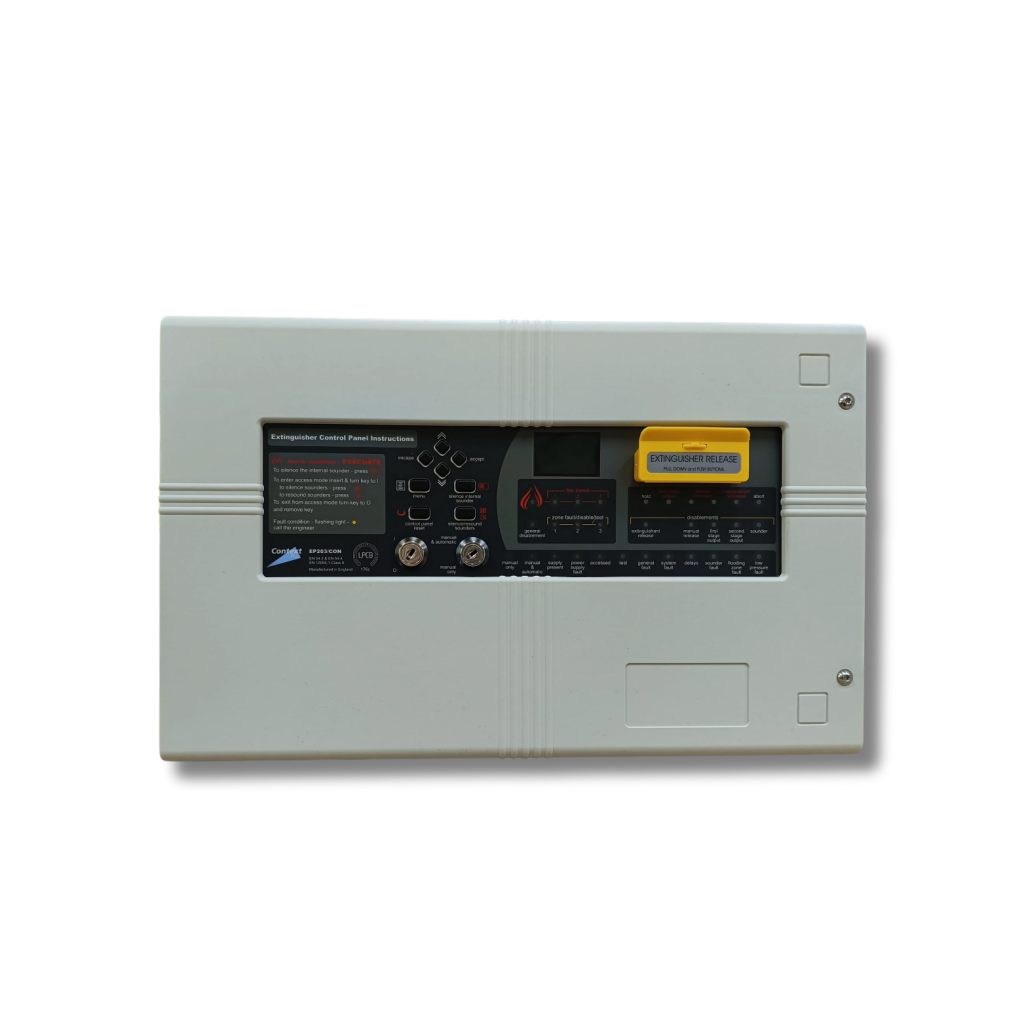
Featuring an intuitive 128 x 64 pixel 2-colour graphic display that gives clear and concise feedback to the user, installer and commissioning engineer, the panel also includes six monitored inputs, a time stamped log, adjustable flood times and volt-free changeover relays for fire, local fire, 1st stage active, 2nd stage active, extractor fan and fault.
The panel is supplied in an elegantly styled, durable enclosure with all of its electronics – apart from its powerful 3A EN54-4 switch mode PSU – mounted on a detachable metal bridge plate for ease of installation.
- One of the most powerful extinguisher panels of its class on the market with easy to program capability.
- Includes three conventional detector circuits & sounder circuits (2 x 1st stage and 1 x 2nd stage) which are all line monitored for open and short circuit faults.
- Able to program any combination of activated detector zones to automatically activate the extinguishant release sequence, which can be set to operate with or without a delay.
- Minimum six monitored inputs are provided, including Hold and Abort for suspending or cancelling the release sequence at anytime.
- Adjustable flood times.
- Alarm counter to record the number of occasions the panel has been in alarm.
- Time-stamped log.
- Support for an optional relay expansion board to provide reset, mode, discharged, hold and abort outputs.
- Support for up to two Solenoids or multiple Metrons type actuators and volt-free changeover relay contacts for fire, local fire, 1st stage active, 2nd stage active, extract fan and fault.
- System expansion for extra flexibility
- Can be connected to the EP203 via a monitored RS485 bus to include up to eight flush or surface remote status units, each with their own displays, manual release mechanisms and mode switches.
- Single gang economy status units without displays (8 per system).
- A host of other ancillary devices including system line terminators and hold off/abort buttons.
| Power Supply Specification | |
| Mains supply voltage | 230Vac, 50/60Hz |
| Internal power supply | 24Vdc nominal |
| Max. output current | 3A@230Vac |
| Power rating (including charging) | 1.5A cont., 3A peak |
| Battery type |
2 x 12Vdc, 7Ahr VRLA type, connected in series
|
| Battery charge current | 0.7A |
| Earth fault monitoring | YES |
| Mains supply/battery charger monitored for failure | YES |
| Batteries monitored for disconnection and failure | YES |
| Quiescent current drain on mains fail | 40mA approx. |
| Detector Circuit Specification | |
| Number of conventional detector circuits | 3 @ 21-28Vdc |
| Line monitored for open and short circuit faults | YES |
| Max. cable length per circuit | 250m |
| Max. no. of smoke/heat detectors per circuit | 20 |
| Max. combined no. of detectors & manual call points per circuit | 32 |
| Zone quiescent current | 2mA max. |
| End-of-line resistor value | 6K8 ohm ± 5%, 0.25W |
| Sounder Circuit Specification | |
| No. of conventional circuits |
3 (two x 1st stage, one x 2nd stage)
|
| Line monitored for open and short circuit faults | YES |
| Sounder outputs rating |
21-28Vdc, fused @200mA per circuit
|
| Max. sounder cable length per circuit | 50m |
| Max. number of polarised sounders per circuit | 10 @ 20mA each |
| End-of-line resistor value | 6K8 ohm ± 5%, 0.25W |
| Extinguishant release outputs | |
| Extinguishant release output |
21-28Vdc, rated at 1A for 5mins.
|
| Extinguishant release time delay |
Adjustable 0-60 seconds (1 second steps)
|
| Extinguishant release duration |
Adjustable 1-300 seconds (1 second steps)
|
| Extinguishant release flooding time |
Adjustable 60-1800 seconds (1 second steps)
|
| Extinguishant output end-of-line |
“Terminator” circuitry EOL (Part No. EP214)
|
| Dimensions (W x H x D) | |
| Dimensions |
Back box = 439mm x 276mm x 70mm approx. (metal); Lid = 467mm x 293mm x 29mm approx. (plastic)
|
| Auxiliary outputs | |
| No. of auxiliary outputs * |
6 (Fire, Local Fire, Extract Fan, 1st Stage, 2nd Stage, Fault)
|
| Relay contact rating | 30Vdc, 1A max. |
| * Note that 5 additional relay outputs (Reset, Mode Switch, Discharged, Hold, Abort) are available on the EP212 relay output expansion card | |
| Monitored Inputs | |
| Number of monitored inputs and type |
6 (Manual Release, Flow Switch, Low Pressure, Mode, Hold, Abort)
|
| Thresholds |
8k to 2k ohms (normal); 1.8k to 200 ohms (active), 150 to 0 ohms (short circuit)
|
| End-of-line resistor value | 6K8± 5%, 0.25W |
| Controls & Indicators | |
| Status Display Unit |
128 x 64 pixel graphic LCD unit, two-colour backlight
|
| LCD ‘Access Level 1’ Menus: |
• Display Faults • Display Disablements • Zones in Test • Lamp Test • Alarm Counter
|
| LCD ‘Access Level 2’ Menus: |
• Display Faults • Display Disablements • Zones in Test • Lamp Test • Alarm Counter • Set Time/Date • Event Log
• Display Contrast • Disablements |
| LCD ‘Access Level 3’ Menus: |
• Display Faults • Display Disablements • Zones in Test • Display RSUs • Disablements • Commissioning • Engineering
|
| Controls (2 x keyswitches) |
• Accessed • Manual Only or Manual & Automatic
|
| Controls (push buttons) |
• Menu • Silence Internal Sounder •Control Panel Reset • Silence/Resound Sounders • Scroll up • Scroll down • Escape
• Accept • Extinguisher Release (housed in yellow casing). |
| Indicators (LEDs) |
• General Fire • Fire Zones (x3) • General Disablement • Zone Fault/Disable/Test (x3) • Hold • First Stage Output • Release Imminent (x2) • Extinguishant Released • Abort • Disablements (Extinguishant Release, Manual Release, First Stage Output, Second Stage Output, Sounder) • Manual Only • Manual & Automatic • Supply Present • PSU Fault • Accessed • Test • General Fault • System Fault • Delays
• Sounder Fault • Flooding Zone Fault • Low Press Fault. |
| Internal control (push button) |
Access Level 3 Switch (located on Main Control PCB)
|