

CFP Panel
CFP PANEL
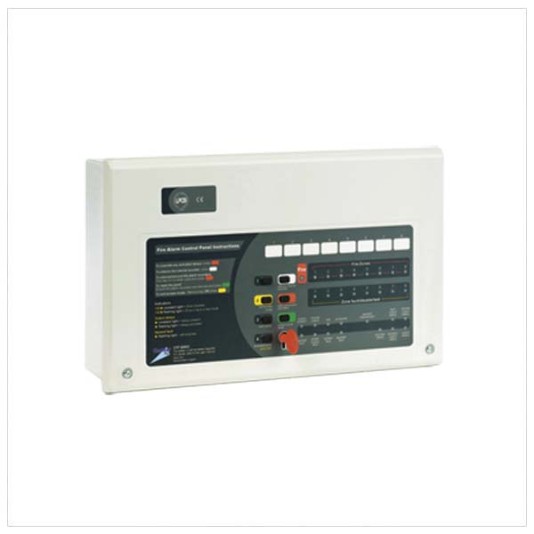
LPCB certified to the latest revisions of EN54 parts 2 and 4, our new-look super-enhanced CFP conventional fire panel offers an array of user and installer-friendly features at a very competitive price.
Supplied in an attractive flush or surface mountable plastic enclosure, 2, 4 and 8 zone versions are available, each featuring four conventional sounder circuits, class change and alert inputs, on-board fire and fault relays and combined keypad/keyswitch entry.
A wide range of engineering functions are also provided including selectable zone delays, coincidence and non-latching zone facilities. Comprehensive test and fault finding facilities are also provided.
- LPCB certified to the latest versions of EN54 Parts 2 and 4
- Intuitive user-friendly interface with colour-coded buttons and combined keypad/keyswitch entry to access level 2
- 2, 4 or 8 zone circuits (dependent on model purchased)
- Four conventional sounder circuits
- Integral 1.5A EN54-4/A2 compliant switch mode PSU
- Wide range of engineering functions including zone test, coincidence*, zone delay and non-latching zones*
- Two on-board relays (Fire and Fault)
- Two open-collector outputs (Remote and Reset)
- Class change’ and alert inputs
- Installer-friendly design accommodates easy first fix and straightforward maintenance
- Attractive flush or surface mountable plastic lid and enclosure – no bezel required
- Low quiescent current
- Multiple indicators
- End of line units included (one per zone)
- MAncillary system expansion connections provided for up to eight two-wire repeaters (one CFP761 network driver card required per system) and optional CFP relay boards
- Space for two x 12V 3.2Ah VRLA batteries
| Power Supply Specification | |
| Mains supply voltage | 230V 50/60Hz |
| Mains rated current | 350mA maximum |
| Internal power supply |
19V – 28.5V (27V nominal). Ripple 7V maximum (battery fault)
|
| Total output current limited to |
1.5A @ 230Vac (ImaxA = 146mA)
|
| Supply and battery charger monitored for failure |
YES (battery charger is also temperature compensated)
|
| Batteries monitored for disconnection and failure | YES |
| Batteries protected against deep discharge |
YES (Deep discharge cut off approx. 21 volts)
|
| Max. battery size and type |
2 x 12V 3.2Ah VRLA connected in series (use YUASA NP3.2-12 for LPCB approved systems)
Minimum battery size = 1.2Ah |
| Mains fuse |
240V 1A HRC ceramic 20mm compliant with IEC (EN60127 PT2)
|
| Battery fuse |
1.6A F 20mm compliant with IEC (EN60127 PT2)
|
| Current draw from battery (Mains failed) | 1.5A maximum |
| Detector Circuit Specification | |
| Number of circuits/zones |
2 (CFP702-4), 4 (CFP704-4) or 8 (CFP704-8)
|
| Max cable length per circuit | 500 metres |
| Cable type |
Fire resistant screened cable, minimum conductor size 1mm2
|
| Connector blocks |
Plug-on type, largest acceptable conductor size 1.5mm2
|
| Line monitored for open circuit and short circuit |
YES – DC monitoring
|
| Line monitored for detector removal |
YES – end of line monitoring device modules provided
|
| Max. allowable impedance (each conductor) | 20 Ohm |
| Max. cable capacitance | 0.27uF |
| Call point resistor value | 470 to 680 Ohm |
| Max. number of smoke/heat detectors per zone | 25 |
| Max. combined number of detectors & call points | 32 per zone
|
|
Sounder Circuit Specification
|
|
| Number of circuits | 4 |
| Max cable length per circuit | 500 metres |
| Cable type |
Fire resistant screened cable, minimum conductor size 1mm2
|
| Connector blocks |
Plug-on type, largest acceptable conductor size 1.5mm2
|
| End of line resistor value |
6800 ohm 5% Tol. 0.25W (blue, grey, red, gold)
|
| Each circuit monitored for open and short circuit |
YES – reverse voltage DC monitoring. Indicated by common fault
|
| Alarm voltage |
27V maximum, 20V minimum (final battery voltage)
|
| Sounder circuit fuses (one per circuit) |
Resettable type (200mA min. hold current; 400mA max. trip current; 50mA when tripped. Reset when faults removed)
|
| Max. total sounder output current to all outputs | 4 x 200mA = 800mA |
| Max. No. of bells @ 25mA | 32 |
| Max. No. of electronic sounders @ 20mA |
40 (sounders must be polarised)
|
| Auxiliary Relay Outputs | |
| Aux. Fire relay output (AUX) |
Voltage-free single pole changeover; Max switching current 1A; Max. switching voltage 30Vdc voltage 30Vdc
|
| Fault relay output (FAULT) |
Voltage-free single pole changeover; Max switching current 1A; Max. switching
|
| Auxiliary Open Collector Outputs | |
| Reset output (RESET) |
Non-monitored open collector type; Active during reset cycle; Max. sink current 30mA; Max. open circuit voltage 27Vdc
|
| Remote output (REM) |
Non-monitored open collector type; Active during any unsilenced fire condition (provided all relevant delays have expired); Max. sink current 30mA; Max. open circuit voltage 27Vdc
|
| 24V aux power output (for use with the above) |
Output protected by a resettable fuse (100mA min. hold current). Resets when fault removed
|
| Auxiliary Inputs | |
| Class Change (makes sounders sound continuously) |
Connect to OV to trigger. Max. input voltage 27V (non-latching)
|
| Alert (makes sounders pulse intermittently) |
Connect to OV to trigger. Max. input voltage 27V (non-latching)
|
| User & Engineer Controls | |
| General user controls (access level one) | User & Engineer Controls |
| Authorised user controls (access level two) | “Silence alarm sounders; Activate alarm sounders; Reset the system; Test the lamps; (Entry via keypad code or keyswitch); Disable/enable zones; Disable/enable fault output; Disable/enable remote output; Disable/enable sounders; Disable/enable auxiliary output; Disable/enable output delays” |
| Engineer controls (access level three) |
Program coincidence (double knock); Invoke one man walk test; Program delays; Set up zones for non-latching operation; Program sounders to resound (or not resound) when a new zone enters alarm; Enter fault diagnostic facilities
|
| Indicators | |
| External indicators |
General fire; Zone fire; Zone fault; Zone disabled; Zone test; Supply present; Remote output activated; Remote output status; Test; Accessed; General disablement; Fault output status; General fault; System fault; Repeater fault; System status; Sounder status; Power supply fault; Auxiliary output status; Output delays
|
| Internal indicators |
System fault (distinguishes between watchdog, site memory and phase lock loop faults); Zone fault (distinguishes between open circuit and short circuit faults); Hazardous voltages present; Repeater fault (indicates which repeaters, if fitted, are faulty)
|
| Dimensions | |
| Physical size |
Size = 380 x 235 x 96mm approx.
|
| Weight |
1.75kg (without batteries)
|
| Operating conditions | |
| The components are selected to operate within their specification when the environmental conditions outside the enclosure comply with class 3k3 of IEC 721-3-3:1978. Temperature range: -5 to + 40°C. Maximum relative humidity: 95% |